Thursday, October 19, 2017

Cisco WLC/Mobility Express (Air-AP1850 series AP) Configuration and Preparing APs to Associate with the WLC AP


######################## Cisco L3 Switch Ports configuration ###########################
Switch(config)#vlan 99
Switch(config-vlan)#name MGT_WLC
Switch(config)#vlan 151
Switch(config-vlan)#name WiFi_Vlan151_Employee

Switch(config)#vlan 152
Switch(config-vlan)#name WiFi_Vlan152_Guest

Switch(config)#interface vlan 99
Switch(config-if)#
%LINK-5-CHANGED: Interface Vlan99, changed state to up
Switch(config-if)#ip address 192.168.99.1 255.255.255.0

Switch(config)#interface vlan 151
Switch(config-if)#
%LINK-5-CHANGED: Interface Vlan151, changed state to up
Switch(config-if)#ip address 192.168.151.1 255.255.255.0

Switch(config)#interface vlan 152
Switch(config-if)#
%LINK-5-CHANGED: Interface Vlan152, changed state to up
Switch(config-if)#ip address 192.168.152.1 255.255.255.0

Switch(config)#ip dhcp pool MGT_WLC_AP
Switch(dhcp-config)#network 192.168.99.0 255.255.255.0
Switch(dhcp-config)#default-router 192.168.99.1

Switch(config)#ip dhcp pool WiFi_Vlan151_cilent
Switch(dhcp-config)#network 192.168.151.0 255.255.255.0
Switch(dhcp-config)#default-router 192.168.151.1

Switch(config)#ip dhcp pool WiFi_L7_client
Switch(dhcp-config)#network 192.168.152.0 255.255.255.0
Switch(dhcp-config)#default-router 192.168.152.1


Switch(config)#interface fa0/1
Switch(config-if)#switchport trunk encapsulation dot1q
Switch(config-if)#switchport mode trunk
Switch(config-if)#switchport trunk native vlan 99
Switch(config-if)#switchport trunk allowed vlan 99,151,152

Switch(config)#interface fa0/2
Switch(config-if)#switchport trunk encapsulation dot1q
Switch(config-if)#switchport mode trunk
Switch(config-if)#switchport trunk native vlan 99
Switch(config-if)#switchport trunk allowed vlan 99,151,152

Switch(config)#interface fa0/3
Switch(config-if)#switchport trunk encapsulation dot1q
Switch(config-if)#switchport mode trunk
Switch(config-if)#switchport trunk native vlan 99
Switch(config-if)#switchport trunk allowed vlan 99,151,152

N.B. For Cisco, all ports must have to be trunk and must have to use native vlan for management. Allow all vlan for the trunk port including MGT vlan.
For Juniper, All ports must have to be trunk and must have to use native vlan for management. Allow all vlan for the trunk port excluding MGT vlan.

####################### WLC-AP (Air-AP1850) configuration #######################

APs are two types. One is Mobility express/standalone device which can be a wireless lan controller (WLC) with an access point (AP) and other type is only access point (AP).


Before start, we have to reset the WLC-AP (Air-AP1850) and connect the WLC-AP with Laptop by console cable .

1. Therefore, press on the reset button of the WLC-AP (Air-AP1852i) and then connect wlc-ap to fa0/1 trunk port of Cisco L3 switch. Press the button for 25 sec then it will reset.

2. When reset completed, the following step should be completed accordingly.

Starting the Initial Configuration Wizard

(Cisco Controller)
Cisco Aironet 1850 Series Mobility Express
Welcome to the Cisco Wizard Configuration Tool
Use the '-' character to backup
Would you like to terminate autoinstall? [yes]: yes
Enter Administrative User Name (24 characters max): root
Enter Administrative Password (3 to 24 characters)   : abc12345
Re-enter Administrative Password                                 : ********
System Name [Cisco_1a:62:20] (31 characters max): WLC_Demo
Enter Country Code list (enter 'help' for a list of countries) [US]: help
Enter the country code list (e.g. US,CA,MX) max=30.
Supported Country Codes:
AE, AL, AR, AT, AU, BA, BB, BE, BG, BH, BM, BN, BO,
BR, BY, CA, CH, CL, CM, CN, CO, CR, CY, CZ, DE, DK,
DO, DZ, EC, EE, EG, EL, ES, FI, FJ, FR, GB, GH, GI,
GR, HK, HR, HU, ID, IE, IL, IO, IN, IQ, IS, IT, J4,
JM, JO, KE, KN, KW, KZ, LB, LI, LK, LT, LU, LV, LY,
MA, MC, ME, MK, MN, MO, MT, MX, MY, NG, NL, NO, NZ,
OM, PA, PE, PH, PK, PL, PR, PT, PY, QA, RO, RS, RU,
SA, SE, SG, SI, SK, TH, TI, TN, TR, TW, UA, US, UY,
VE, VN, ZA
Enter Country Code list (enter 'help' for a list of countries) [US]: CN
Configure a NTP server now? [YES][no]: no
Configure the system time now? [YES][no]: yes
Enter the date in MM/DD/YY format: 10/18/17
Enter the time in HH:MM:SS format: 14:04:00
Enter timezone location index (enter 'help' for a list of timezones): help
  1. (GMT-12:00) International Date Line
  2. (GMT-11:00) Samoa                   3. (GMT-10:00) Hawaii
  4. (GMT -9:00) Alaska     5. (GMT -8:00) Pacific Time
  6. (GMT -7:00) Mountain Time   7. (GMT -6:00) Central Time
  8. (GMT -5:00) Eastern Time        9. (GMT -4:00) Altantic Time
 10. (GMT -3:00) Buenos Aires     11. (GMT -2:00) Mid-Atlantic
 12. (GMT -1:00) Azores                  13. (GMT) London, Lisbon, Dublin
 14. (GMT +1:00) Amsterdam,Berlin,Rome            15. (GMT +2:00) Jerusalem
 16. (GMT +3:00) Baghdad                             17. (GMT +4:00) Muscat, Abu Dhabi
 18. (GMT +4:30) Kabul                                   19. (GMT +5:00) Karachi, Tashkent
 20. (GMT +5:30) Colombo, New Delhi     21. (GMT +5:45) Kathmandu
 22. (GMT +6:00) Almaty, Novosibirsk      23. (GMT +6:30) Rangoon
 24. (GMT +7:00) Hanoi, Bangkok               25. (GMT +8:00) HongKong, Beijing
 26. (GMT +9:00) Tokyo, Osaka, Seoul      27. (GMT +9:30) Darwin
 28. (GMT+10:00) Sydney, Melbourne     29. (GMT+11:00) Solomon Is.
 30. (GMT+12:00) Auckland, Fiji
Enter timezone location index (enter 'help' for a list of timezones): 22
Management Interface IP Address Configuration [STATIC][dhcp]: STATIC
Management Interface IP Address: 192.168.99.25
Management Interface Netmask: 255.255.255.0
Management Interface Default Router: 192.168.99.1
Cleaning up Provisioning SSID

Create Management DHCP Scope? [yes][NO]: no
Employee Network Name (SSID)?: Employee_demo
Employee Network Security? [PSK][enterprise]: psk
Employee PSK Passphrase (8-63 characters)? : 12345678
Re-enter Employee PSK Passphrase                 : 12345678
Enable RF Parameter Optimization? [YES][no]: yes
Client Density [TYPICAL][Low][High]:
Traffic with Voice [NO][Yes]: yes
Configuration correct? If yes, system will save it and reset. [yes][NO]: yes

Cleaning up Provisioning SSID
Configuration saved!
Resetting system with new configuration...

Then system will reboot.

3.Connect to the wifi which SSID is "Employee_demo". Open the browser and write down the
address "https://192.168.99.25". After that login to the WLC with the username (root) & password "abc12345" which was given earlier.

Logging in to Cisco Mobility Express (ME)


4.


Understanding the Mobility Express(ME) Controller Web Interface
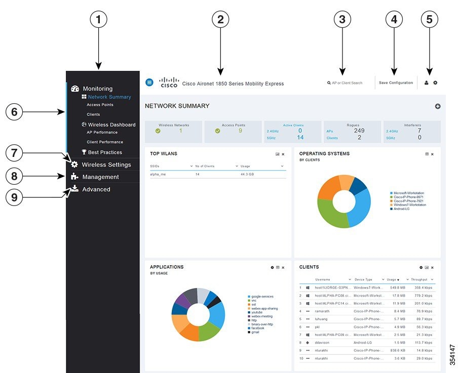

No.
Web Interface Section or Feature
1
The side pane of the web interface. This is main navigational pane using which you can navigate to the various sub-sections in the web interface.
2
The title of the web interface. It indicates the AP model of the master AP (on which the integrated controller functionality is currently operating)
3
Search for an AP or client using its MAC address.
4
Click to save the current controller configuration to the NVRAM.
5
Click to view the current system information or to log off the controller web interface.
6
The Mobility Express Network Monitoring section.
7
The Wireless Settings section, where you can administer associated APs, manage WLANs, WLAN user accounts, and guest user accounts.
8
The Management section, where you can set management access parameters, manage admin accounts, network time, and perform software updates.
9
The Advanced section, where you can set SNMP settings, sys log settings, and perform a reset to factory default.

4. From the web Panel go to Wireless Settings>>Add new WLAN and do accordingly to the following snapshots.


5. After that we will join another AP to the WLC. Therefore, connect another AP (Air-AP1850) to the switch port fa0/2 and wait for a while. Then check on the WLC web panel and you will see the second AP has been joined.


Reference Links:
https://www.cisco.com/c/en/us/td/docs/wireless/access_point/mob_exp/1/user_guide/b_ME_User_Guide/getg_start.html


Sunday, September 24, 2017

Multi-chassis LAG Configuration (LACP)


Before Starting LAG configuration, See the below details.

## Link aggregation group (LAG)
## Link Aggregation Control Protocol (LACP)

When configuring LAGs, consider the following guidelines:

You must configure the LAG on both sides of the link.
You must set the interfaces on either side of the link to the same speed.
You can configure and apply firewall filters on a LAG.
You can optionally configure LACP for link negotiation.
You can optionally configure LACP for link protection.


-------------------------------------------------------For Site A----------------------------------------------------

1.The first step is to specify the number of aggregated links on the switch. This command is to specify number of bundle (aggregated interface) you want to create.:

set chassis aggregated-devices ethernet device-count 1

Here we will create one bundle links each having two Ethernet from different VC member (switch).

2.Next, we have to remove the logical unit configuration from the interfaces that are to be bundled, as logical units are not allowed on aggregated links:

delete interfaces ge-0/0/0 unit 0
delete interfaces ge-1/0/0 unit 0

3.Next, set the interfaces to use LACP (802.3ad) and to be members of a logical aggregated ethernet port (ports begin with ae).
To associate physical interface with an aggregated Ethernet interface, hit the following command:

set interfaces ge-0/0/0 ether-options 802.3ad ae0
set interfaces ge-1/0/0 ether-options 802.3ad ae0


4.Then we need to set the LACP mode for our new aggregated interface. We’ll make the Juniper side Active, so that it initiates the transmissison of LACP packets:

set interfaces ae0 aggregated-ether-options lacp active


5.Finally, we need to set the aggregated link to be a trunk, and tell it which VLAN’s to trunk.
Configure interface parameters like VLANs, MTU, port-mode, etc. in ae interfaces:

set interfaces ae0 unit 0 family ethernet-switching port-mode trunk

set vlans NOC vlan-id 10
set vlans IT vlan-id 20
set interfaces ae0 unit 0 family ethernet-switching vlan members IT
set interfaces ae0 unit 0 family ethernet-switching vlan members NOC
set interfaces ge-0/0/6 unit 0 family ethernet-switching vlan members IT
set interfaces ge-1/0/6 unit 0 family ethernet-switching vlan members IT
set interfaces ge-0/0/5 unit 0 family ethernet-switching vlan members NOC
set interfaces ge-1/0/5 unit 0 family ethernet-switching vlan members NOC


6.Veryfing:
root> show lacp interfaces
Aggregated interface: ae0
    LACP state:       Role   Exp   Def  Dist  Col  Syn  Aggr  Timeout  Activity
      ge-0/0/0          Actor    No    No   Yes  Yes  Yes   Yes     Fast        Active
      ge-0/0/0        Partner    No    No   Yes  Yes  Yes   Yes     Fast       Active
      ge-1/0/0          Actor    No    No   Yes  Yes  Yes   Yes     Fast        Active
      ge-1/0/0       Partner    No    No   Yes  Yes  Yes   Yes     Fast        Active
    LACP protocol:        Receive State  Transmit State          Mux State
      ge-0/0/0                  Current   Fast periodic Collecting distributing
      ge-1/0/0                  Current   Fast periodic Collecting distributing


root> show ethernet-switching interfaces

Interface    State     VLAN members        Tag   Tagging  Blocking
ae0.0             up            IT                         20     tagged   unblocked
                                     NOC                     10     tagged   unblocked

root> show vlans

Name           Tag     Interfaces
IT                 20       ae0.0*, ge-0/0/6.0, ge-1/0/6.0
NOC            10       ae0.0*, ge-0/0/5.0*, ge-1/0/5.0
default
                                ge-0/0/1.0, ge-0/0/2.0, ge-0/0/3.0, ge-0/0/4.0,
                                ge-0/0/7.0, ge-0/0/8.0, ge-0/0/9.0, ge-0/0/10.0,
                                ge-0/0/11.0, ge-0/0/12.0, ge-0/0/13.0, ge-0/0/14.0,
                                ge-0/0/15.0, ge-0/0/16.0, ge-0/0/17.0, ge-0/0/18.0,
                                ge-0/0/19.0, ge-0/0/20.0, ge-0/0/21.0, ge-0/0/22.0,
                                ge-0/0/23.0, ge-0/0/24.0, ge-0/0/25.0, ge-0/0/26.0,
                                ge-0/0/27.0, ge-0/0/28.0, ge-0/0/29.0, ge-0/0/30.0,
                                ge-0/0/31.0, ge-0/0/32.0, ge-0/0/33.0, ge-0/0/34.0,
                                ge-0/0/35.0, ge-0/0/36.0, ge-0/0/37.0, ge-0/0/38.0,
                               ge-0/0/39.0, ge-0/0/40.0, ge-0/0/41.0, ge-0/0/42.0,
                               ge-0/0/43.0, ge-0/0/44.0, ge-0/0/45.0, ge-0/0/46.0,
                               ge-0/0/47.0, ge-1/0/1.0, ge-1/0/2.0, ge-1/0/3.0,
                               ge-1/0/4.0, ge-1/0/7.0, ge-1/0/8.0, ge-1/0/9.0,
                               ge-1/0/10.0, ge-1/0/11.0, ge-1/0/12.0, ge-1/0/13.0,
                               ge-1/0/14.0, ge-1/0/15.0, ge-1/0/16.0, ge-1/0/17.0,
                               ge-1/0/18.0, ge-1/0/19.0

-------------------------------------------------For Site B---------------------------------------------------------

1.The first step is to specify the number of aggregated links on the switch. This command is to specify number of bundle (aggregated interface) you want to create.:

set chassis aggregated-devices ethernet device-count 1

Here we will create one bundle links each having two Ethernet from different VC member (switch).

2.Next, we have to remove the logical unit configuration from the interfaces that are to be bundled, as logical units are not allowed on aggregated links:

delete interfaces ge-0/0/0 unit 0
delete interfaces ge-1/0/0 unit 0

3.Next, set the interfaces to use LACP (802.3ad) and to be members of a logical aggregated ethernet port (ports begin with ae).
To associate physical interface with an aggregated Ethernet interface, hit the following command:

set interfaces ge-0/0/0 ether-options 802.3ad ae0
set interfaces ge-1/0/0 ether-options 802.3ad ae0


4.Then we need to set the LACP mode for our new aggregated interface. We’ll make the Juniper side Active, so that it initiates the transmissison of LACP packets:

set interfaces ae0 aggregated-ether-options lacp active


5.Finally, we need to set the aggregated link to be a trunk, and tell it which VLAN’s to trunk.
Configure interface parameters like VLANs, MTU, port-mode, etc. in ae interfaces:

set interfaces ae0 unit 0 family ethernet-switching port-mode trunk
set vlans NOC vlan-id 10
set vlans IT vlan-id 20
set interfaces ae0 unit 0 family ethernet-switching vlan members IT
set interfaces ae0 unit 0 family ethernet-switching vlan members NOC
set interfaces ge-0/0/6 unit 0 family ethernet-switching vlan members IT
set interfaces ge-1/0/6 unit 0 family ethernet-switching vlan members IT
set interfaces ge-0/0/5 unit 0 family ethernet-switching vlan members NOC
set interfaces ge-1/0/5 unit 0 family ethernet-switching vlan members NOC


6.Veryfing:
root> show lacp interfaces
Aggregated interface: ae0
    LACP state:       Role   Exp   Def  Dist  Col  Syn  Aggr  Timeout  Activity
      ge-0/0/0       Actor    No    No   Yes  Yes  Yes   Yes     Fast    Active
      ge-0/0/0     Partner    No    No   Yes  Yes  Yes   Yes     Fast    Active
      ge-1/0/0       Actor    No    No   Yes  Yes  Yes   Yes     Fast    Active
      ge-1/0/0     Partner    No    No   Yes  Yes  Yes   Yes     Fast    Active
    LACP protocol:        Receive State  Transmit State          Mux State
      ge-0/0/0                  Current   Fast periodic Collecting distributing
      ge-1/0/0                  Current   Fast periodic Collecting distributing


root> show ethernet-switching interfaces
Interface    State  VLAN members        Tag   Tagging  Blocking
ae0.0        up     IT                  20    tagged   unblocked
                    NOC                 10    tagged   unblocked

root> show vlans
Name           Tag     Interfaces
IT             20
                       ae0.0*, ge-0/0/6.0, ge-1/0/6.0
NOC            10
                       ae0.0*, ge-0/0/5.0*, ge-1/0/5.0
default
                       ge-0/0/1.0, ge-0/0/2.0, ge-0/0/3.0, ge-0/0/4.0,
                       ge-0/0/7.0, ge-0/0/8.0, ge-0/0/9.0, ge-0/0/10.0,
                       ge-0/0/11.0, ge-0/0/12.0, ge-0/0/13.0, ge-0/0/14.0,
                       ge-0/0/15.0, ge-0/0/16.0, ge-0/0/17.0, ge-0/0/18.0,
                       ge-0/0/19.0, ge-0/0/20.0, ge-0/0/21.0, ge-0/0/22.0,
                       ge-0/0/23.0, ge-0/0/24.0, ge-0/0/25.0, ge-0/0/26.0,
                       ge-0/0/27.0, ge-0/0/28.0, ge-0/0/29.0, ge-0/0/30.0,
                       ge-0/0/31.0, ge-0/0/32.0, ge-0/0/33.0, ge-0/0/34.0,
                       ge-0/0/35.0, ge-0/0/36.0, ge-0/0/37.0, ge-0/0/38.0,
                       ge-0/0/39.0, ge-0/0/40.0, ge-0/0/41.0, ge-0/0/42.0,
                       ge-0/0/43.0, ge-0/0/44.0, ge-0/0/45.0, ge-0/0/46.0,
                       ge-0/0/47.0, ge-1/0/1.0, ge-1/0/2.0, ge-1/0/3.0,
                       ge-1/0/4.0, ge-1/0/7.0, ge-1/0/8.0, ge-1/0/9.0,
                       ge-1/0/10.0, ge-1/0/11.0, ge-1/0/12.0, ge-1/0/13.0,
                       ge-1/0/14.0, ge-1/0/15.0, ge-1/0/16.0, ge-1/0/17.0,
                       ge-1/0/18.0, ge-1/0/19.0

Wednesday, September 20, 2017

HA configuration for Juniper SRX340 Router


HA configuration for SRX340
-------------------------------------------------------------------------------------------------------------

Before starting configuration of my srx340 for cluster, remove some configuration items to avoid some post configuration errors.
In each srx do the followings:

First delete all logical interface which are used for control link/plane(ge-0/0/1)
& Data/fabric link/plane(ge-0/0/2).
***Note:Control link and Data link interface are varying for different Models.

delete system host-name
delete vlans
delete interfaces vlan
delete security
delete interfaces ge-0/0/1
delete interfaces ge-0/0/2
delete interfaces ge-0/0/3 unit 0 family ethernet-switching
delete interfaces ge-0/0/4 unit 0 family ethernet-switching


After this operation make sure there is no ethernet-switching left:
root@srx1# show | match ethernet-switching | count
Count: 0 lines
[edit]
root@srx1#


Then Physically connect the two devices and ensure that they are the same models.
For example,on the SRX340 Services Gateway, connect the dedicated control ports on node 0 and node 1.
***Note: For SRX300, SRX320, SRX340, and SRX345 devices, connect ge-0/0/1 on node 0 to ge-0/0/1 on node 1.

1.Set the two devices to cluster mode and reboot the devices. You must enter the following 
operational mode commands on both devices, for example:

On node 0:
---------------
user@host> set chassis cluster cluster-id 1 node 0 reboot
On node 1:
---------------
user@host> set chassis cluster cluster-id 1 node 1 reboot

#After reboot if you check the prompt of srx1, you will see the prompt changes like below:

{hold:node0}
root@srx1>
{secondary:node0}
root@srx1>
{primary:node0}
root@srx1>

#Check cluster status:

root@srx1> show chassis cluster status
Cluster ID: 1
Node                  Priority          Status    Preempt  Manual failover

Redundancy group: 0 , Failover count: 1
    node0                   1           primary        no       no
    node1                   1           secondary      no       no

***Note: After clustering occurs, For SRX340 device, the ge-0/0/1 interface on node 1 changes to ge-5/0/1.


2.Set up hostnames and management IP addresses on the first node only (srx-nd0) for each device using configuration groups.These configurations are specific to each device and are unique to its specific node.

set groups node0 system host-name srx-nd0
set groups node0 interfaces fxp0 unit 0 family inet address 192.168.33.1/24
set groups node1 system host-name srx-nd1
set groups node1 interfaces fxp0 unit 0 family inet address 192.168.33.2/24

3.Set the 'apply-groups' command so that the individual configurations for each node set by the previous commands are applied only to that node.

set apply-groups "${node}"

4.Define the interfaces used for the fab connection (data plane links for RTO sync) by using physical ports ge-0/0/2 from each node. These interfaces must be connected back-to-back. Configure fabric links on the first node only (srx-nd0):

set interfaces fab0 fabric-options member-interfaces  ge-0/0/2
set interfaces fab1 fabric-options member-interfaces  ge-5/0/2

#After commit, config should sync into srx-nd1 node as well. Now check cluster interfaces status:

root@srx1> show chassis cluster interfaces
Control link 0 name: fxp1
Control link status: Up

Fabric interfaces:
Name    Child-interface    Status
fab0       fe-0/0/5          up
fab0
fab1       fe-2/0/5          up
fab1
Fabric link status: Up


5.Set up redundancy group 0 for the Routing Engine failover properties, and set up redundancy group 1 (all interfaces are in one redundancy group in this example) to define the failover properties for the 
redundant Ethernet interfaces. A cluster without an RG is useless. Lets create a redundancy group and test it.RG0 is used for control plane and RG1 will be our service RG.
set chassis cluster reth-count 2
set chassis cluster redundancy-group 0 node 0 priority 200
set chassis cluster redundancy-group 0 node 1 priority 100
set chassis cluster redundancy-group 1 node 0 priority 200
set chassis cluster redundancy-group 1 node 1 priority 100


6.Set up interface monitoring to monitor the health of the interfaces and trigger redundancy group failover.

******Note: Juniper does not recommend Interface monitoring for redundancy group 0 because it causes the control plane to switch from one node to another node in case interface flap occurs.

set chassis cluster redundancy-group 1 interface-monitor ge-0/0/3 weight 255
set chassis cluster redundancy-group 1 interface-monitor ge-0/0/4 weight 255
set chassis cluster redundancy-group 1 interface-monitor ge-5/0/3 weight 255
set chassis cluster redundancy-group 1 interface-monitor ge-5/0/4 weight 255

***Note: Interface failover only occurs after the weight reaches 0.

#Let's check the cluster configuration:
{primary:node0}
root@SRX> show configuration chassis cluster

reth-count 2;
redundancy-group 0 {
    node 0 priority 200;
    node 1 priority 100;
}
redundancy-group 1 {
    node 0 priority 200;
    node 1 priority 100;
    preempt;
    interface-monitor {
        ge-0/0/3 weight 255;
        ge-0/0/4 weight 255;
        ge-5/0/3 weight 255;
        ge-5/0/4 weight 255;
    }
}


7.Set up the redundant Ethernet (reth) interfaces and assign the redundant interface to a zone.


set interfaces ge-0/0/3 gigether-options redundant-parent reth0
set interfaces ge-5/0/3 gigether-options redundant-parent reth0
set interfaces reth0 redundant-ether-options redundancy-group 1
set interfaces reth0 unit 0 family inet address 198.51.100.1/24

set interfaces  ge-0/0/4 gigether-options redundant-parent reth1
set interfaces  ge-5/0/4 gigether-options redundant-parent reth1
set interfaces reth1 redundant-ether-options redundancy-group 1
set interfaces reth1 unit 0 family inet address 203.0.113.233/24

set security zones security-zone Trusted
set security zones security-zone Untrusted
set security zones security-zone Trusted host-inbound-traffic system-services all
set security zones security-zone Untrusted host-inbound-traffic system-services all
set security zones security-zone Untrust interfaces reth1.0
set security zones security-zone Trust interfaces reth0.0

#If you want to create a subinterface with vlan tagging do the following(Optional)
set interfaces reth0 vlan-tagging
set interfaces reth0 unit 150 vlan-id 150
set interfaces reth0 unit 150 family inet address 192.168.150.200/24
set interfaces reth1 unit 0 family inet address 10.16.9.1/24

set security zones security-zone Trusted interfaces reth0.150
set security zones security-zone Untrusted interfaces reth1.0


Case 01:
If we deactivate interface monitor it doesn't effect on HA.


 Verification
------------------------------------------------------------------------------------------------------------

show chassis cluster status
show chassis cluster interfaces
show chassis cluster statistics
show chassis cluster control-plane statistics
show chassis cluster data-plane statistics
show chassis cluster status redundancy-group 1


show configuration
-------------------------------------------------------------------------------------------------------
root@srx# run show configuration
## Last commit: 2017-08-07 16:41:31 GMT+6 by root
version 15.1X49-D90.7;
groups {
    node0 {
        system {
            host-name srx-nd0;
        }
        interfaces {
            fxp0 {
                unit 0 {
                    family inet {
                        address 192.168.33.1/24;
                    }
                }
            }
        }
    }
    node1 {
        system {
            host-name srx-nd1;
        }
        interfaces {
            fxp0 {
                unit 0 {
                    family inet {
                        address 192.168.33.2/24;
                    }
                }
            }
        }
    }
}
apply-groups "${node}";
system {
    auto-snapshot;
    time-zone GMT+6;
    root-authentication {
        encrypted-password "$5$ZsCeZsruXu$TZ8Kvvzb/mxQOMqf8AxJkFqW.r5OZFnrdagxRl8LSH."; ## SECRET-DATA
 
    }
    services {
        ssh;
        telnet;

        }
    }
 
}
chassis {
    cluster {
        reth-count 2;
        redundancy-group 0 {
            node 0 priority 200;
            node 1 priority 100;
        }
        redundancy-group 1 {
            node 0 priority 200;
            node 1 priority 100;
            preempt;
            interface-monitor {
                ge-0/0/3 weight 255;
                ge-0/0/4 weight 255;
                ge-5/0/3 weight 255;
                ge-5/0/4 weight 255;
            }
        }
    }
}
security {
    screen {
        ids-option untrust-screen {
            icmp {
                ping-death;
            }
            ip {
                source-route-option;
                tear-drop;
            }
            tcp {
                syn-flood {
                    alarm-threshold 1024;
                    attack-threshold 200;
                    source-threshold 1024;
                    destination-threshold 2048;
                    timeout 20;
                }
                land;
            }
        }
    }
    nat {
        source {
            rule-set nsw_srcnat {
                from zone Internal;
                to zone Internet;
                rule nsw-src-interface {
                    match {
                        source-address 0.0.0.0/0;
                        destination-address 0.0.0.0/0;
                    }
                    then {
                        source-nat {
                            interface;
                        }
                    }
                }
            }
        }
    }
    policies {
        from-zone Internal to-zone Internet {
            policy All_Internal_Internet {
                match {
                    source-address any;
                    destination-address any;
                    application any;
                }
                then {
                    permit;
                }
            }
        }
    }
    zones {
        security-zone Internal;
        security-zone Internet {
            screen untrust-screen;
        }
        security-zone Trusted {
            host-inbound-traffic {
                system-services {
                    all;
                }
            }
            interfaces {
                reth0.0;
            }
        }
        security-zone Untrusted {
            host-inbound-traffic {
                system-services {
                    all;
                }
            }
            interfaces {
                reth1.0;
            }
        }
    }
}
interfaces {
    ge-0/0/3 {
        gigether-options {
            redundant-parent reth0;
        }
    }
    ge-0/0/4 {
        gigether-options {
            redundant-parent reth1;
        }
    }
    ge-5/0/3 {
        gigether-options {
            redundant-parent reth0;
        }
    }
    ge-5/0/4 {
        gigether-options {
            redundant-parent reth1;
        }
    }
    fab0 {
        fabric-options {
            member-interfaces {
                ge-0/0/2;
            }
        }
    }
    fab1 {
        fabric-options {
            member-interfaces {
                ge-5/0/2;
            }
        }
    }
    fxp0 {
        unit 0 {
            family inet;
        }
    }
    reth0 {
   
        redundant-ether-options {
            redundancy-group 1;
        }
        unit 0 {
            family inet {
                address 198.51.100.1/24;
            }
        }
    }
    reth1 {
        redundant-ether-options {
            redundancy-group 1;
        }
        unit 0 {
            family inet {
                address 203.0.113.233/24;
            }

Sunday, August 27, 2017

Configuring a QFX5100 two-members Virtual Chassis with a Preprovisioned Configuration

QFX Virtual Chassis Overview
----------------------------------------
A QFX Series Virtual Chassis is a flexible, scaling switch solution for supported combinations of QFX3500, QFX3600, QFX5100, and QFX5110 switches. EX4300 switches can also be included in some configurations of a QFX Series Virtual Chassis..

In a QFX Series Virtual Chassis, you can interconnect up to ten standalone switches in the following
combinations into one logical device, and manage the logical device as a single chassis:

QFX5110 switches or a combination of QFX5110 and QFX5100 switches (a non-mixed Virtual Chassis)
QFX5100 switches (a non-mixed Virtual Chassis)
QFX5100 switches with any combination of QFX3500, QFX3600, or EX4300 switches (a mixed mode Virtual Chassis)
QFX3500 switches or QFX3600 switches, or a combination of QFX3500 and QFX3600 switches (a non-mixed Virtual Chassis)
QFX3500 or QFX3600 switches with EX4300 switches, or a combination of all three types of switches (a mixed mode Virtual Chassis)

The advantages of connecting multiple switches into a Virtual Chassis include better-managed bandwidth at a network layer, simplified configuration and maintenance because multiple devices can be managed as a single device, increased fault tolerance and high availability(HA) because a Virtual Chassis can remain active and network traffic can be redirected to other member switches when a single member switch fails, and a flatter, simplified Layer 2 network topology that minimizes or eliminates the need for loop prevention protocols such as Spanning Tree Protocol (STP).

You set up a Virtual Chassis by configuring Virtual Chassis ports (VCPs) on the member switches, and interconnecting the switches using the VCPs . VCPs are responsible for passing all data and control traffic between member switches in the Virtual Chassis. The following ports on QFX Series switches that support Virtual Chassis can be configured into VCPs to form a QFX Series Virtual Chassis:

Any 100-Gbps or 40-Gbps QSFP28 ports on QFX5110 switches
Any non-channelized 40-Gbps QSFP+ ports on QFX3500, QFX3600, QFX5100, or QFX5110 switches
Any fixed 10-Gbps SFP+ ports on QFX Series switches with these ports

You can increase VCP bandwidth between member switches by configuring multiple interfaces between the same two switches into VCPs. When multiple VCPs interconnect the same two member switches, a Link Aggregation Group (LAG) or bundle is automatically formed when the VCPs are on interfaces supporting identical speeds. For example, if you have two 40-Gbps QSFP+ interfaces configured as VCPs between member switches, a LAG with two member links with 80Gbps of total bandwidth is formed. However, 10-Gbps SFP+ and 40-Gbps QSFP+ interfaces configured as VCPs
will not become members of the same VCP LAG.

----------------------------------
Before configuration note
----------------------------------
1. IF the new member switch is running a version of Junos OS that is different than the version of
Junos OS running on the Virtual Chassis, then ensure that the correct version of Junos OS is or
will be installed on the new member switch by performing software update or automatic software update enable.

root> request system software add ftp://ip address/jinstall-qfx-5-14.1X53-D42.3-domestic-signed.tgz no-validate no-copy
user@device# set virtual-chassis auto-sw-update package-name ftp://hostname/pathname/package-name

--------------------------------------------------------------------------------------------------------------------------
Configuring a QFX5100 two-member Virtual Chassis with a Preprovisioned Configuration File:
--------------------------------------------------------------------------------------------------------------------------

1.Make a list of the serial numbers of all the switches to be connected in a
  Virtual Chassis configuration.

S/N: TR02171XXXXX
S/N: TR021712XXXX

2.Note the desired role (routing-engine or line-card) of each switch. If you
  configure the member with a routing-engine role, it is eligible to function in
  the master or backup role. If you configure the member with a line-card role, it
  is not eligible to function in the master or backup role.

3.Power on only the switch with S/N: TR02171XXXXX that you plan to use as the master switch.


-------------------------------------------------
For SW with S/N: TR02171XXXXX
-------------------------------------------------


4.After the reboot is complete, specify the preprovisioned configuration mode:

[edit virtual-chassis]
user@switch# set preprovisioned

5.Specify all the members that you want included in the Virtual Chassis, listing each switch’s
serial number with the desired member ID and role:

[edit virtual-chassis]

user@switch# set member 0 serial-number TR02171XXXXX role routing-engine
user@switch# set member 1 serial-number TR021712XXXX role routing-engine


6.(Recommended for a two-member Virtual Chassis) Disable the split and merge
feature:

[edit virtual-chassis]
user@switch# set no-split-detection

-------------------------------------------------
For SW with S/N: TR021712XXXX 
-------------------------------------------------

7. Power on only the switch with S/N: TR021712XXXX that you plan to use as the Backup switch.

After the boot is complete, specify the preprovisioned configuration mode:

[edit virtual-chassis]
user@switch# set preprovisioned

8.Specify all the members that you want included in the Virtual Chassis, listing each switch’s serial number with the desired member ID and role:
[edit virtual-chassis]

user@switch# set member 0 serial-number TR02171XXXXX role routing-engine
user@switch# set member 1 serial-number TR021712XXXX role routing-engine

9.(Recommended for a two-member Virtual Chassis) Disable the split and merge
feature:

[edit virtual-chassis]
user@switch# set no-split-detection

10.Finaly connect the qsfp+ cable to the et-0/0/53 for both switch according to the picture.

N.B. Now wait for 5 mintues. Changing any configuration from master sw do "commit synchronous" command. 

-------------------
Verifying VC:
-------------------

##From SW with S/N: TR02171XXXXX

root> show virtual-chassis

Preprovisioned Virtual Chassis
Virtual Chassis ID: 9b18.70fb.c786
Virtual Chassis Mode: Enabled
                                                Mstr           Mixed Route Neighbor List
Member ID  Status       Serial No              Model           prio  Role       Mode  Mode  ID  Interface
0 (FPC 0)    Prsnt    TR02171XXXXX qfx5100-48t-6q 129   Master*     N      VC      1   vcp-255/0/53
1 (FPC 1)    Prsnt    TR021712XXXX qfx5100-48t-6q  129  Backup      N      VC      0   vcp-255/0/53

##From SW with S/N: TR021712XXXX

root> show virtual-chassis

Preprovisioned Virtual Chassis
Virtual Chassis ID: 9b18.70fb.c786
Virtual Chassis Mode: Enabled
                                                Mstr           Mixed Route Neighbor List
Member ID  Status   Serial No    Model          prio  Role      Mode  Mode ID  Interface
0 (FPC 0)  Prsnt    TR02171XXXXX qfx5100-48t-6q 129   Master*      N  VC   1  vcp-255/0/53
1 (FPC 1)  Prsnt    TR021712XXXX qfx5100-48t-6q 129   Backup       N  VC   0  vcp-255/0/53

------------------------------------------------------------------
login to the member switch of the Virtual Chassis:
------------------------------------------------------------------
root>request session member <member-id>
>>>Here member ID '0' is for master and '1' for Backup<<<


------------------------------------------------------------
Mastership switching of the Virtual Chassis:
------------------------------------------------------------

{master:member0-re0}
root> request virtual-chassis routing-engine master switch
Do you want to continue ? [yes,no] (no)yes

{backup:member0-re0}
root>

NOTE:Before you issue the request virtual-chassis routing-engine master switch command from the master router or switch in the Virtual Chassis, make sure that the system configuration is synchronized between the master and backup router or switch. If the configuration is not synchronized, or if you attempt to issue the request virtual-chassis routing-engine master switch command from the backup router or switch instead of from the master router or switch, the device displays an error message and rejects the command.If you issue the request virtual-chassis routing-engine master switch command when the Virtual Chassis is in a transition state (for example, the backup router or switch is disconnecting from the Virtual Chassis),
the device does not process the command.

Wednesday, August 23, 2017

Route based IPSEC Multiple site to site VPN Configuration with two Junipers SRX340 & CISCO 2900 Routers


-----------------------------------------------------------------------------------------------------------
IPSEC Multiple site to site VPN Configuration with two Junipers & CISCO Routers:
-----------------------------------------------------------------------------------------------------------

SRX340-HQ   : Untrust IP- 1.1.1.1/30, Trust IP-10.1.1.1/24, st0.0 IP: 172.16.0.1/30
                          Untrust IP- 2.2.2.1/30,                                    st0.1 IP: 172.16.1.1/30

SRX340-West : Untrust IP- 2.2.2.2/30, Trust IP-10.3.3.1/24, st0.0 IP: 172.16.1.2/30
CISCO-East    : Untrust IP- 1.1.1.2/30, Trust IP-10.2.2.1/24, tunnel 0 IP:172.16.0.2/30

----------------------
##Juniper HQ:
----------------------
set interfaces ge-0/0/0 unit 0 family inet address 1.1.1.1/30
set interfaces ge-0/0/1 unit 0 family inet address 2.2.2.1/30
set interfaces ge-0/0/3 unit 0 family inet address 10.1.1.1/24
set interfaces st0 unit 0 family inet address 172.16.0.1/30
set interfaces st0 unit 0 family inet mtu 1400
set interfaces st0 unit 1 family inet address 172.16.1.1/30
set interfaces st0 unit 1 family inet mtu 1400

set security zones security-zone trust interfaces st0.0
set security zones security-zone trust interfaces st0.1
set security zones security-zone trust interfaces ge-0/0/3.0

set security zones security-zone untrust interfaces ge-0/0/0.0
set security zones security-zone untrust interfaces ge-0/0/1.0

Phase 01 for Site "A":
----------------------
## IKE proposal
set security ike proposal IKE-Proposal lifetime-seconds 28800
set security ike proposal IKE-Proposal authentication-method pre-shared-keys
set security ike proposal IKE-Proposal authentication-algorithm sha1
set security ike proposal IKE-Proposal encryption-algorithm aes-128-cbc
set security ike proposal IKE-Proposal dh-group group2

## IKE policy
set security ike policy IKE-Poly mode main
set security ike policy IKE-Poly proposals IKE-Proposal
set security ike policy IKE-Poly pre-shared-key ascii-text tawfique

##(For cisco-East)IKE gateway with peer IP address, IKE policy and outgoing interfac
set security ike gateway IKE-GW ike-policy IKE-Poly
set security ike gateway IKE-GW address 1.1.1.2
set security ike gateway IKE-GW external-interface ge-0/0/0.0

##(For SRX340-west)IKE gateway with peer IP address, IKE policy and outgoing interfac
set security ike gateway IKE-GW2 ike-policy IKE-Poly
set security ike gateway IKE-GW2 address 2.2.2.2
set security ike gateway IKE-GW2 external-interface ge-0/0/1.0


## Security zones, assign interfaces to the zones & host-inbound services for each zone
set security zones security-zone Untrust host-inbound-traffic system-services ike


Phase 02 for Site "A":
----------------------
## IPSec proposal
set security ipsec proposal IPSEC-Proposal lifetime-seconds 3600
set security ipsec proposal IPSEC-Proposal protocol esp
set security ipsec proposal IPSEC-Proposal authentication-algorithm hmac-sha1-96
set security ipsec proposal IPSEC-Proposal encryption-algorithm aes-128-cbc

## IPSec Policy
set security ipsec policy IPSEC-Poly proposals IPSEC-Proposal

##(For cisco-East) IPSec VPN
set security ipsec vpn IPSEC-VPN bind-interface st0.0
set security ipsec vpn IPSEC-VPN ike ipsec-policy IPSEC-Poly
set security ipsec vpn IPSEC-VPN ike gateway IKE-GW
set security ipsec vpn IPSEC-VPN establish-tunnels immediately

##(For SRX340-west) IPSec VPN
set security ipsec vpn IPSEC-VPN2 bind-interface st0.1
set security ipsec vpn IPSEC-VPN2 ike ipsec-policy IPSEC-Poly
set security ipsec vpn IPSEC-VPN2 ike gateway IKE-GW2
set security ipsec vpn IPSEC-VPN2 establish-tunnels immediately


#Routing Option(For cisco-East)
set routing-options static route 10.2.2.0/24 next-hop st0.0

#Routing Option(For SRX340-west)
set routing-options static route 10.3.3.0/24 next-hop st0.1

-------------------------
####CISCO East:
-------------------------

Router(config)#interface GigabitEthernet0/0
Router(config-if)#ip add 1.1.1.2 255.255.255.252
Router(config-if)#no sh

Router(config)#interface GigabitEthernet0/1
Router(config-if)#ip add 10.2.2.1 255.255.255.0
Router(config-if)#no sh

Phase 01(IKE isakmp configuration)
----------------------------------
Router(config)#crypto isakmp policy 1
Router(config-isakmp)#authentication pre-share
Router(config-isakmp)#encryption aes 128
Router(config-isakmp)#hash sha
Router(config-isakmp)#lifetime 28800
Router(config-isakmp)#group 2
Router(config-isakmp)#exit
Router(config)#crypto isakmp key tawfique address 1.1.1.1


Phase 02(IPsec VPN configuration)
----------------------------------
Router(config)#crypto ipsec transform-set MY-VPN esp-aes 128 esp-sha-hmac
Router(cfg-crypto-trans)# mode transport

#create IPsec profile
Router(config)#crypto ipsec profile VPNPROFILE
Router(ipsec-profile)# set transform-set MY-VPN

#create tunnel interface with IP and give IPsec protection
Router(config)#interface tunnel 0
Router(config-if)#ip add 172.16.0.2 255.255.255.252
Router(config-if)#tunnel source 1.1.1.2
Router(config-if)#tunnel destinations 1.1.1.1
Router(config-if)#tunnel mode ipsec ipv4
Router(config-if)#tunnel protection ipsec profile VPNPROFILE
Router(config-if)#ip mtu 1400

#create static route
Router(config)#ip route 10.1.1.0 255.255.255.0 tunnel 0

----------------------
##Juniper West:
----------------------

set interfaces ge-0/0/0 unit 0 family inet address 2.2.2.2/30
set interfaces ge-0/0/3 unit 0 family inet address 10.3.3.1/24
set interfaces st0 unit 0 family inet address 172.16.1.2/30
set interfaces st0 unit 0 family inet mtu 1400


set security zones security-zone trust interfaces st0.0
set security zones security-zone trust interfaces ge-0/0/3.0

set security zones security-zone untrust interfaces ge-0/0/0.0


Phase 01 for Site "A":
----------------------
## IKE proposal
set security ike proposal IKE-Proposal lifetime-seconds 28800
set security ike proposal IKE-Proposal authentication-method pre-shared-keys
set security ike proposal IKE-Proposal authentication-algorithm sha1
set security ike proposal IKE-Proposal encryption-algorithm aes-128-cbc
set security ike proposal IKE-Proposal dh-group group2

## IKE policy
set security ike policy IKE-Poly mode main
set security ike policy IKE-Poly proposals IKE-Proposal
set security ike policy IKE-Poly pre-shared-key ascii-text tawfique

##(For SRX340-HQ)IKE gateway with peer IP address, IKE policy and outgoing interfac
set security ike gateway IKE-GW ike-policy IKE-Poly
set security ike gateway IKE-GW address 2.2.2.1
set security ike gateway IKE-GW external-interface ge-0/0/0.0


## Security zones, assign interfaces to the zones & host-inbound services for each zone
set security zones security-zone Untrust host-inbound-traffic system-services ike


Phase 02 for Site "A":
----------------------
## IPSec proposal
set security ipsec proposal IPSEC-Proposal lifetime-seconds 3600
set security ipsec proposal IPSEC-Proposal protocol esp
set security ipsec proposal IPSEC-Proposal authentication-algorithm hmac-sha1-96
set security ipsec proposal IPSEC-Proposal encryption-algorithm aes-128-cbc

## IPSec Policy
set security ipsec policy IPSEC-Poly proposals IPSEC-Proposal

##(For SRX340-HQ) IPSec VPN
set security ipsec vpn IPSEC-VPN bind-interface st0.0
set security ipsec vpn IPSEC-VPN ike ipsec-policy IPSEC-Poly
set security ipsec vpn IPSEC-VPN ike gateway IKE-GW
set security ipsec vpn IPSEC-VPN establish-tunnels immediately


#Routing Option(For SRX340-HQ)
set routing-options static route 10.1.1.0/24 next-hop st0.0


------------------------------------------
#Verifying the VPN for Juniper:
------------------------------------------
1) show security ike security-associations
2) show security ipsec security-associations
3) show security ipsec statistics
4) show route

------------------------------------------
#Verifying the VPN for Cisco:
------------------------------------------
1) show crypto isakmp sa
2) show crypto ipsec sa
3) show crypto ipsec statistics
4) show route